Setup Sweep Window
When Sweep Settings are selected, the following window shows the primary setting elements. Note that by default, the first channel of the instrument is enabled.
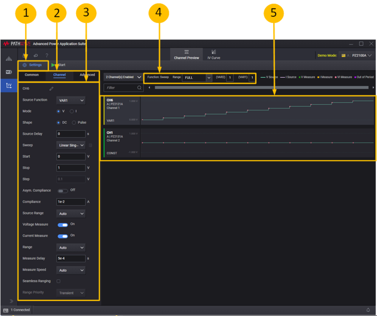
- Select Settings to display the Setup Sweep settings.
- Selectable options include Common, Channel, and Advanced.
- Displays the Common, Channel, and Advanced settings.
- Displays the Signal Graph scroll settings.
- Displays the Output Signal graph.
Common Settings
Common settings set the parameters common to all channels.
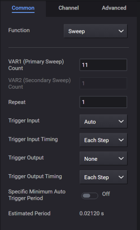
| VAR1 (Primary Sweep) Count | Sets the primary sweep count. Must be 1 ~ 10000. |
| VAR2 (Secondary Sweep) Count
|
Sets the secondary sweep count. Must be 1 ~ 10. |
| Repeat
|
Sets the repeat count. Must be 1 ~ 100. |
| Trigger (for B2900 only) | Auto: Automatically adjusts step periods. Timer: Generates fixed step periods. |
| Trigger Input (for PZ2100 only) |
Sets the trigger input. The input is common for all channels. For Ext1 – Ext7, the external IO Port are connected to the INT4 internal trigger line, which has been configured to the TINPut function. |
| Trigger Input Polarity (for PZ2100 only) |
Only applies when Trigger Input is set to Ext1 – Ext7 or MExt1 – MExt2. Selections are:
For Ext1 – Ext7: Sets the polarity of the external IO Port. |
| Trigger Input Timing (for PZ2100 only) |
Sets the trigger input timing. A trigger input for each step |
| Trigger Output (for PZ2100 only) |
Sets the trigger output. The output is common for all channels. For Ext1 – Ext7, the external IO Port are connected to the INT5 internal trigger line, which has been configured to the TOUTput function. |
| Trigger Output Polarity (for PZ2100 only) |
Only applies when Trigger Output is set to Ext1 – Ext7 or MExt1 – MExt2. Selections are:
For Ext1 – Ext7: Sets the polarity of the external IO Port. |
| Trigger Output Timing (for PZ2100 only) |
Sets the trigger output timing. A trigger output for each step |
| Specific Minimum Auto Trigger Period | This checkbox appears when the trigger mode is set to Auto. When checked, the period field is shown. Enter the minimum period time. When unchecked, the period time is set automatically. If you want to set the pulse after the delay, check this box and set the minimum period time. |
| Estimated Period | Sets the step period time. |
Channel Settings
Channel settings set the basic sweep setting parameters for the selected channel.
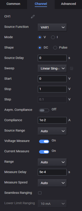
| Source Function | Selects the source function [ VAR1/VAR2/CONST/OPEN/IGNORE ].
|
| Mode
|
Selects Voltage [V] source or Current [I] source. |
| Shape | Selects the output signal shape [ DC/Pulse ]
. |
| Source | Sets the source value. This parameter can be set when Function=CONST and Shape=DC. |
| Source Delay | Sets the source delay time. This parameter cannot be set on following conditions. Function=CONST and Shape=DC Function=VAR2 and Shape=DC. |
| Pulse Width | Sets the pulse width time. This parameter cannot be set when Shape=DC. |
| Pulse Peak | Sets the pulse peak value. This parameter is available when Function=CONST and Shape=Pulse. |
| Source | Sets the constant source value. This parameter is available when Function=CONST and Shape=DC |
| Pulse Base | Sets the pulse base value. This parameter cannot be set when Shape=DC. |
| Sweep | Selects the sweep mode. [ Linear Single/Linear Double/Log Single/Log Double/List ] If the List mode is selected, the right side of the button will be enabled. To edit the list data, click this button. This parameter cannot be set when Function=CONST. |
| Start | Sets the Linear/Logarithm sweep start value. For logarithm sweep, the [Start * Stop] value should be grater than zero. This parameter cannot be set when Function=CONST or Sweep=List. |
| Stop | Sets the Linear/Logarithm sweep stop value. For logarithm sweep, the [Start * Stop] value should be grater than zero. This parameter cannot be set when Function=CONST or Sweep=List. |
| Step | Shows the Linear/Logarithm sweep step value. For linear sweep, the step voltage or current value is displayed. For logarithm sweep, the step ratio [%] value is displayed. If the Start & Stop values are invalid for logarithm sweep, an error occurs. This parameter is not displayed for List sweep. |
| Asym. Compliance (for PZ2100A) | Turns asymmetrical compliance on or off. |
| + Compliance (for PZ2100A) | Sets the compliance value for the positive side. This parameter applies when Asym. Compliance is On. |
| - Compliance (for PZ2100A) | Sets the compliance value for the negative side. This parameter applies when Asym. Compliance is On. |
| Compliance (for B2900/B2960) | Sets the compliance value. |
| Source Range | Sets the source range. |
| Voltage Measure | Enables/disables voltage measurement. To enable voltage measurement, check this checkbox. |
| Range | Selects the voltage measurement range. This parameter cannot be set for the voltage source mode. Force Range setting is used as the measurement range. |
| Current Measure | Enables/disables current measurement. To enable voltage measurement, check this checkbox. |
| Range | Selects the current measurement range. This parameter cannot be set for the current source mode. Force Range setting is used as the measurement range. |
| Measure Delay | Sets the measure delay time. |
| Measure Speed | Selects the measurement speed [ Auto/Short/Medium/Normal/Long/Manual ]. For Manual, the Aperture Time parameter will be enabled. |
| Aperture Time | Sets the measurement aperture time. This parameter is only displayed when the Measure Speed is Manual. |
| Seamless Ranging (for PZ2130A and PZ2131A only) | Enables/disables seamless ranging. To enable seamless ranging, check this check box. This parameter only applies when the source mode is voltage. |
| Lower Limit Ranging (for PZ2130A and PZ2131A only) | Sets the seamless range lower limit. This parameter only applies when seamless ranging is enabled. |
| Range Priority (for PZ2120A and PZ2121A only) | Sets the pulse range priority (noise, transient or power). This parameter applies only when the Mode is I and the Source Function is set to Pulse. |
Advanced Channel Settings
This sets the advanced sweep setting parameters for the selected channel.
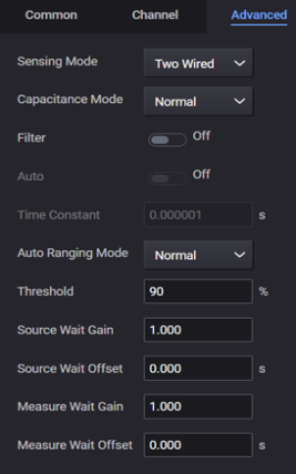
| Sensing Mode (for B2900/B2960) | Selects the sensing mode [ Two Wired/Four Wired ]. |
| Capacitance Mode (for B2900/B2960) | Selects the capacitance mode [ Normal/High ]. |
| Operation Mode (for PZ2100A) | Selects the operation mode [ Normal/Power Supply/High Capacitance/Laser Diode ]
Power Supply option only for PZ2120A, PZ2121A, PZ2130A and PZ2131A. High Capacitance option only for PZ2121A and PZ2120A. Laser Diode option only for PZ2120A and PZ2121A. |
| Filter
|
Selects the output filter ON/OFF. |
| Auto | Selects the automatic filter ON/OFF. |
| Time Constant | Sets the filter time constant value [ time = 1/ ( 2 * pi * cutoff_freq ) ]. |
| Auto Ranging Mode | Selects the auto ranging mode [Normal/Resolution/Speed]. |
| Threshold | Sets the auto-ranging threshold rate. |
| Source Wait Gain | Sets the gain value used for calculating the source wait time. [wait time = gain * initial wait time + offset] This parameter is only valid for the auto trigger mode. |
| Source Wait Offset | Sets the offset value used for calculating the source wait time. [wait time = gain * initial wait time + offset] This parameter is only valid for the auto trigger mode. |
| Measure Wait Gain | Sets the gain value used for calculating the measure wait time. [wait time = gain * initial wait time + offset] This parameter is only valid for the auto trigger mode. |
| Measure Wait Offset | Sets the offset value used for calculating the measure wait time. [wait time = gain * initial wait time + offset] This parameter is only valid for the auto trigger mode. |
| External Low Noise Filter (for PZ2130A and PZ2131A) | Enables or disables the external low noise filter. |
| Output Resistance (for B2960) | Selects output resistance ON/OFF. |
| Series Res. (for B2960) | Sets the series resistance for voltage output. |
| Shunt Res. (for B2960) | Sets the shunt resistance for current output. |
Signal Graph Scroll Settings
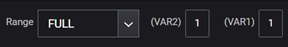
| Preview Range | Shows/selects the range for the Signal group as follows: FULL: shows the full range VAR2: shows the VAR2 sweep range VAR1: shows the VAR1 sweep range STEP: shows 1 step range 1 (+): the Input step number sets the primary sweep count. Must be 1 ~ 10000. If the view range is less than four steps, the level and timing parameters are shown on the Signal graph. |
| Offset VAR2 | Shows/selects the VAR2 number of the graph's left-end step. |
| Offset VAR1
|
Shows/selects the VAR2 number of the graph's left-end step. |
Output Signal Graph
This graph shows the channel output signal and measurement points.The lines show the output setting, and the dots show the measurement start points.

When the total step number (VAR1 * VAR2 ) exceeds 10000, preview is automatically turned OFF.